How SPC works
SPC combines both stereo and photoclinometry techniques together to render an accurate topographical model.
.
.
Stereo technique:
Stereo uses 2 images of the same terrain (in similar illumination conditions) where the spacecraft was in 2 close but different positions when the photograph was taken. Stereo then mathematically determines the distance from the space craft where the two vectors cross. Using this data a topographical map can be created. The result of stereo photography results in two slightly offset images also known as a stereogram that using 3D glasses displays a 3D model. This technique does not provide any albedo data.

Photoclinometry technique:
Photoclinometry uses variations in reflected light to determine the slope of a surface. Using 3 images this technique finding the observed flux is a simple function of incidence angle, and albedo with photometric correlations. The results of this function give slope-x, slope-y, and albedo. An error common with this technique is that is it difficult to distinguish shadow accurately.

.
SPC Works Best With
- A minimum of three images (typically >30, this study 4)
- Two stereo images
- Emission angles 45° (acceptable 35-48°, limit 5-60°)
- Stereo angle 90° (acceptable 70-110°, limit 10-120°)
- Incidence angle 0° (acceptable 0-20°, limit 0-60°)
- Three photoclinometry images
- Emission 0° (acceptable 0-20°, limit 0-60°)
- Incidence angles 45° (acceptable 30-50°, limit 0-60°)
- Variation in illumination geometry of 90° (acceptable 40-90°, limit 10-120°). This refers to having different positions of the Sun with respect to the observed target.
.
.

.
.
.

How SPC uses the images:
SPC improves upon standard photoclinometry by utilizing and adding stereo photography data. SPC provides 2D solutions which helps avoid errors because it solves for the entire surface where as 1D solutions may not allow for a maximum slope. SPC is also able to solve for albedo on a pixel-to-pixel basis. Additional because SPC uses multiple images with multiple incidence angles it is able to reduce the impact of noise, blur, cosmic rays, and the photometric response of the surface.
.
.
.
.

The SPC process:
SPC generates many small maps all over the surface of the object. The center points of these small maps are determined by stereo. The interstitial heights are determined by photoclinometry. The images are orthorectified and they are aligned using the images feature to a reference point. This results in every image having control points, which are referred to as Landmarks. These landmarks allow for the spacecrafts pointing and position to be updated. Each landmark has numerous (50+) images
.
.
.
Maplets:
What is the difference between a maplet or a landmark? (They come in pairs.)
- Maplets are a small map that contains multiple landmarks. Maplets provide the data; such as the vectors, the displacement from the normal plane (height) and the albedo.
.

- Landmarks are the meta data and provide the coordinates, pictures and neighboring maplets.
.
Landmark meta data example
AA0001 T
49 0.0007500 SIZE, SCALE(KM)
-1 -1 -1 -1 HORIZON
0.3750000000D-03 0.2120871348D+00 SIGKM, RMSLMK
0.7974410662D-01 -0.5741905971D-03 0.2454077806D+00 VLM
0.9149619937D+00 -0.2081362344D-01 -0.4030028582D+00 UX
0.2381833643D-01 0.9997133017D+00 0.2444690093D-02 UY
0.4028364420D+00 -0.1183565613D-01 0.9151954651D+00 UZ
0.3469010368D-03 0.3725367318D-03 0.6954701621D-03 SIGMA_LMK
PICTURES
P595902930F0 467.45 640.43
P595903597F0 516.23 40.80
P595904281F0 596.99 693.50
P595904947F0 713.34 70.80
P595905631F0 854.09 689.53
P595917125F0 368.92 62.17
P595978335F0 921.60 212.77
M595949288F0 350.24 622.09
M595949718F0 360.75 656.44
.
.
SPC has 4 major functions
1.Importing Images
- Correct flight using dynamics tool
- Gross alignment using register to correctly locate images position
- Autoregister tool to correctly connect landmarks in photos
Support files
PICTLIST.TXT
coverage_p
LIST.TXT
2. Landmarks – Using LITHOS tool
- Create landmarks, add correct or remove images using using
- Modify, rename, adjust size, load height from shapes and Z maps
- Template selected by correlation, manually or created.
- Aligned to picture, manually or Autoalign
Support files
LMKLIST.TXT
3. Batch Processing
- Able to batch process landmarks and topography
- Batch processing is available to transfer information between computers and incorporate it into existing data.
Support files
make_scriptA/P/R.seed
make_script.in
map_coverage.pgm .INN
4. Using the Data
- Visualization can be done using stereomapB, mosaic, display, panorama and surface_imager
- Shape using Dumber, Densify and DensifyA
- Analysis using Geometry, Residuals and shape_info
- Navigation using Regrew, poles and Omega
Support Files:
MAPINFO.TXT
PICTINFO.TXT
LMKINFO.TXT
SHAPE.TXT POLE.TXT
RESIDUALS.pgm
.
.
Error Analysis
As the DTM goes through the process of being perfected at it given resolution it will be defined by the quality of the processing preformed. Some of these steps will need to be repeated multiple times before moving on to the next step.
Tiled
Tiled means that the DTM has undergone the basic stages of latlon-tiling or bigmap_tiling. This does not have any additional processing, just the batch mode.
Correlated
Correlated means that all the landmarks of the DTM are indicating a correlation score (above 0.0000). This means they do not throw the “*” error for find_nofitP.
Imaged
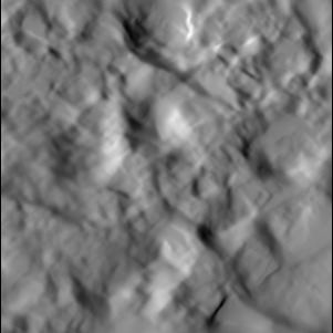
Imaged means that there are at least 5 images for every landmark. While 3 is the minimum, 5 is needed to have a robust DTM that accounts for error. If there are not 5, then a lower number is acceptable; however, it can never be less than 3.
Fitted
Fitted means that there are no maplets with more than 10 “nofits”. No Fit errors are thrown when overlaps is unable to match two maplets that should overlap. This means that there are too many differences between the two maplets for SPC to find common ground. It is common for there to be a few maplets that are missing one or two of their connections with other maplets.
Geometry
Run basic geometry with option 2 to update the spacecraft position and camera vector. You should iterate at least once after.
Residualed Residualed indicates that errors thrown by residuals. Any errors that are marked by “>>” have been corrected. Typically, you would run geometry with option 2 before running residuals. The standard input for this level is: 5 5x GSD GSD. You may choose looser values to get a smaller list first. 5 pixels — image (or maplet) pixels. How close they are. 5x GSD, ground sample distance, 5 times the resolution of the maplets. GSD, ground sample distance
Re-tiled
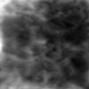
Re-tiled means that the DTM has any holes filled in. For the global scale, use coverage and look for where the missing maplets are. ZMaps can be used if available. For local scale, build a bigmap and look for regions where the maplets were deleted. You can build them missing ones by hand, or you can run the bigmap_tiling procedure.
Sigma’ed
A DTM created by densify or bigmap will have a sigma values, shown by SIGMAS.TXT. All peaks are reduced to < 2xGSD and the average is <GSD of the smallest maplet.
Re-imaged
Here you add images to get just as many as possible, doing processing by hand as needed. More images reduce the amount of error in the model, so adding more images will make the model better.
Image geometry
An evaluation is complete of all images such that all images have at least 4 landmarks defined to set the spacecraft position/pointing
Re-Residualed
This is where you use tighter limits for what throws an error. Typically: 2, 2xGSD, GSD. 2 pixels — image (or maplet) pixels. (How close they are) 2x GSD, ground sample distance, 2 times the resolution of the maplets. GSD, ground sample distance
.
Additional Helpful Information
.
Detailed File Structure
• MAPFILES – stores the topography
• AA0001.MAP – Binary file of center vector, normal plane, delta height and albedo
• LMKFILES – stores the metadata
• AA0001.LMK – Metadata, images, limbs, overlaps
• SHAPEFILES – Reference shape models
• IMAGEFILES – Binary version of the images
• NOMINALS – Unmodified S/C position and pointing
• SUMFILES – Metadata on the images
• Landmarks, limbs, S/C position, pointing, Nav uncertainty
• INIT_LITHOS.TXT – configuration file
• PICTLIST.TXT – list of images
• LMRKLIST .TXT- list of landmarks
• (more info at the wiki: http://sbib.psi.edu/spc_wiki/HomePage)
Nomenclature
• All of SPC is in West Longitude
• IAU requires asteroids to be in East Longitude
• As you travel to the east, longitude values
increase
• Maplet/Landmark names
• Example: DF0000.LMK
• D is latitude
• 20° bins. Valid range A-I
• F is longitude
• 20° bins. Valid range A-R
.
.
.
